- +91 8956063349
- instrumentsmedia@gmail.com
-
GST NUM: 27KSQPS1563C1Z8
Ravika Dead Weight Instruments
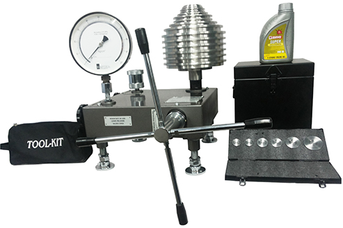
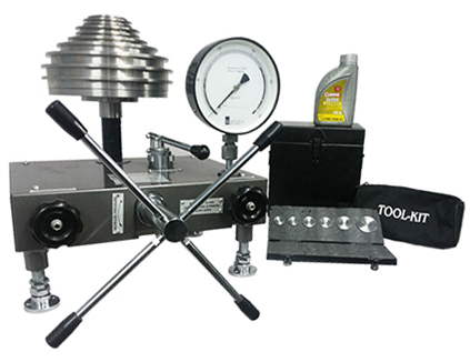
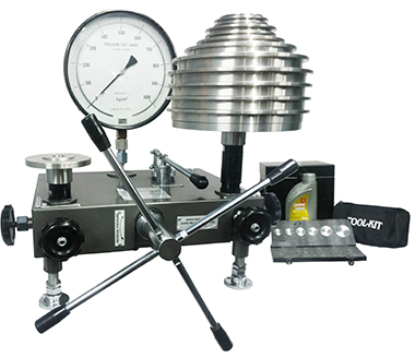
Models of DW 10 series are provided with one large capacity screw pump and a removable oil reservoir with isolating valve in a simple line circuit permitting effective air removal.
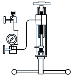
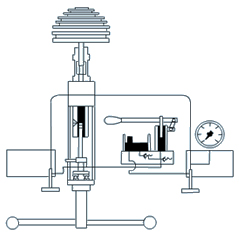
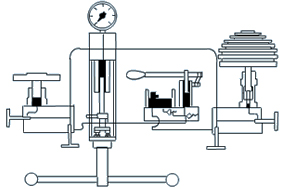
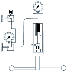
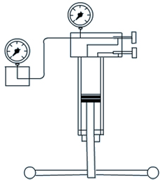
WORKING PRINCIPLE: The Dead Weight Pressure Gauge Testers make use of the relationship between pressure acting on the known area of a vertically free floating piston producing a force balanced by known dead weight.
MAIN COMPONENTS of the tester are :-
Screw Pump: It is used to generate pressure in the circuit of adequate capacity and is operated by a spoked handle which permits easy and accurate setting of pressure.
Free Piston Assembly: It is made of special steel, hardened, tempered, ground and lapped to accurate size and very fine surface finish provides true floating action.
Set of Weights: Each weight is directly marked in convenient values of pressure and is easily stacked on the weight carrier which is placed on to the free piston. The calibration can be provided in various units of pressure measurement namely kgf/cm2, bar, lbf/in2, kPa, KN/m2 as per customer requirement. Weights are available in two material options : MS Phosphated black & SS 304. Storage box is provided for storing weights safely.
Gauge Connector: of 1/2" BSP (female) union for connecting the gauge to be tested. Gauges with other connecting threads may be connected using adoptors provided.
Base Plate: The instrument is mounted on a sturdy base plate provided with levelling screws. The entire circuit is covered by a sheet metal cover.
Incremental Weights: to provide smaller steps (better least count) is available for all models at extra cost.
Calibration / Traceability:Calibration is done against Master Dead Weight Pressure Gauge Tester and Master Dial Pressure Gauges using cross-float method. Our instruments are backed by test certificates traceable to National Standard to meet the requirements of ISO 9000, QS 14000 and other Inspection Agencies.
| MODEL | RANGE (kgf / cm2) | RANGE (lbf / in2) | RANGE (bar) | RANGE (MPa) | ||||||||
| DW10 | Min. | Step | Max. | Min. | Step | Max. | Min. | Step | Max. | Min. | Step | Max. |
| REGULAR | 0.1 | 0.01 | 2.5 | 1 | 0.1 | 40 | 0.1 | 0.01 | 2.5 | 0.01 | 0.001 | 0.25 |
| INC | 0.1 | 0.001 | 2.5 | 1 | 0.005 | 40 | 0.1 | 0.001 | 2.5 | 0.01 | 0.0001 | 0.25 |
| MODEL | RANGE (kgf / cm2) | RANGE (lbf / in2) | RANGE (bar) | RANGE (MPa) | ||||||||
| DW11 | Min. | Step | Max. | Min. | Step | Max. | Min. | Step | Max. | Min. | Step | Max. |
| REGULAR | 0.1 | 0.05 | 6 | 1 | 0.5 | 80 | 0.1 | 0.05 | 6 | 0.01 | 0.005 | 0.6 |
| INC | 0.1 | 0.001 | 6 | 1 | 0.02 | 80 | 0.1 | 0.001 | 6 | 0.01 | 0.0001 | 0.6 |
| MODEL | RANGE (kgf / cm2) | RANGE (lbf / in2) | RANGE (bar) | RANGE (MPa) | ||||||||
| DW12 | Min. | Step | Max. | Min. | Step | Max. | Min. | Step | Max. | Min. | Step | Max. |
| REGULAR | 0.2 | 0.05 | 16 | 2 | 1 | 200 | 0.2 | 0.05 | 16 | 0.02 | 0.005 | 1.6 |
| INC | 0.2 | 0.002 | 16 | 2 | 0.05 | 200 | 0.2 | 0.002 | 16 | 0.02 | 0.0002 | 1.6 |
| MODEL | RANGE (kgf / cm2) | RANGE (lbf / in2) | RANGE (bar) | RANGE (MPa) | ||||||||
| DW13 | Min. | Step | Max. | Min. | Step | Max. | Min. | Step | Max. | Min. | Step | Max. |
| REGULAR | 0.4 | 0.1 | 25 | 5 | 1 | 360 | 0.4 | 0.1 | 25 | 0.04 | 0.01 | 2.5 |
| INC | 0.4 | 0.005 | 25 | 5 | 0.05 | 360 | 0.4 | 0.005 | 25 | 0.04 | 0.0005 | 2.5 |
| MODEL | RANGE (kgf / cm2) | RANGE (lbf / in2) | RANGE (bar) | RANGE (MPa) | ||||||||
| DW14 | Min. | Step | Max. | Min. | Step | Max. | Min. | Step | Max. | Min. | Step | Max. |
| REGULAR | 0.4 | 0.1 | 40 | 5 | 1 | 500 | 0.4 | 0.1 | 40 | 0.04 | 0.01 | 4 |
| INC | 0.4 | 0.005 | 40 | 5 | 0.05 | 500 | 0.4 | 0.005 | 40 | 0.04 | 0.0005 | 4 |
| MODEL | RANGE (kgf / cm2) | RANGE (lbf / in2) | RANGE (bar) | RANGE (MPa) | ||||||||
| DW15 | Min. | Step | Max. | Min. | Step | Max. | Min. | Step | Max. | Min. | Step | Max. |
| REGULAR | 1 | 0.1 | 60 | 10 | 2 | 800 | 1 | 0.1 | 60 | 0.1 | 0.01 | 6 |
| INC | 1 | 0.01 | 60 | 10 | 0.1 | 800 | 1 | 0.01 | 60 | 0.1 | 0.001 | 6 |
| MODEL | RANGE (kgf / cm2) | RANGE (lbf / in2) | RANGE (bar) | RANGE (MPa) | ||||||||
| DW16 | Min. | Step | Max. | Min. | Step | Max. | Min. | Step | Max. | Min. | Step | Max. |
| REGULAR | 1 | 0.1 | 100 | 20 | 5 | 1500 | 1 | 0.1 | 100 | 0.1 | 0.01 | 10 |
| INC | 1 | 0.01 | 100 | 20 | 0.2 | 1500 | 1 | 0.01 | 100 | 0.1 | 0.001 | 10 |
FIELDS OF
APPLICATION:
|
OPERATING
FLUID:
|
||||||||||||||||||||||||||||||||||||||||||||||||||||||||||||||||||||||||||||||||||||||||||||||||||||||||||||||||||||||||||||
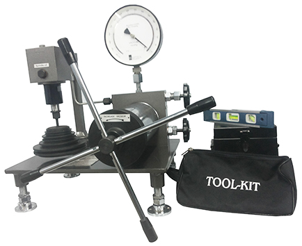
Models of DW 20 and DW 30 series are provided with a lever operated Priming Pump also giving continuous oil delivery for filling up large gauges or even external piping. It is capable of developing 10% of instrument range and with isolating valves at both ends. If form a unique closed circuit for effective air removal.
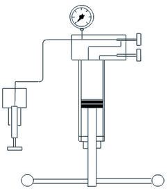
WORKING PRINCIPLE: The Dead Weight Pressure Gauge Testers make use of the relationship between pressure acting on the known area of a vertically free floating piston producing a force balanced by known dead weight.
MAIN COMPONENTS of the tester are :-
Screw Pump: It is used to generate pressure in the circuit of adequate capacity and is operated by a spoked handle which permits easy and accurate setting of pressure.
Free Piston Assembly: It is made of special steel, hardened, tempered, ground and lapped to accurate size and very fine surface finish provides true floating action.
Set of Weights: Each weight is directly marked in convenient values of pressure and is easily stacked on the weight carrier which is placed on to the free piston. The calibration can be provided in various units of pressure measurement namely kgf/cm2, bar, lbf/in2, kPa, KN/m2 as per customer requirement. Weights are available in two material options : MS Phosphated black & SS 304. Storage box is provided for storing weights safely.
Gauge Connector: of 1/2" BSP (female) union for connecting the gauge to be tested. Gauges with other connecting threads may be connected using adoptors provided.
Base Plate: The instrument is mounted on a sturdy base plate provided with levelling screws. The entire circuit is covered by a sheet metal cover.
Incremental Weights: to provide smaller steps (better least count) is available for all models at extra cost.
Calibration / Traceability:Calibration is done against Master Dead Weight Pressure Gauge Tester and Master Dial Pressure Gauges using cross-float method. Our instruments are backed by test certificates traceable to National Standard to meet the requirements of ISO 9000, QS 14000 and other Inspection Agencies.
| MODEL | RANGE (kgf / cm2) | RANGE (lbf / in2) | RANGE (bar) | RANGE (MPa) | ||||||||
| DW21 | Min. | Step | Max. | Min. | Step | Max. | Min. | Step | Max. | Min. | Step | Max. |
| REGULAR | 2 | 0.5 | 160 | 20 | 10 | 2000 | 2 | 0.5 | 160 | 0.2 | 0.05 | 16 |
| INC | 2 | 0.02 | 160 | 20 | 0.5 | 2000 | 2 | 0.02 | 160 | 0.2 | 0.002 | 16 |
| MODEL | RANGE (kgf / cm2) | RANGE (lbf / in2) | RANGE (bar) | RANGE (MPa) | ||||||||
| DW22 | Min. | Step | Max. | Min. | Step | Max. | Min. | Step | Max. | Min. | Step | Max. |
| REGULAR | 4 | 1 | 250 | 40 | 10 | 3600 | 4 | 1 | 250 | 0.4 | 0.1 | 25 |
| INC | 4 | 0.05 | 250 | 40 | 0.5 | 3600 | 4 | 0.05 | 250 | 0.4 | 0.005 | 25 |
| MODEL | RANGE (kgf / cm2) | RANGE (lbf / in2) | RANGE (bar) | RANGE (MPa) | ||||||||
| DW23 | Min. | Step | Max. | Min. | Step | Max. | Min. | Step | Max. | Min. | Step | Max. |
| REGULAR | 5 | 1 | 400 | 50 | 10 | 5000 | 5 | 1 | 400 | 0.5 | 0.1 | 40 |
| INC | 5 | 0.05 | 400 | 50 | 0.5 | 5000 | 5 | 0.05 | 400 | 0.5 | 0.005 | 40 |
| MODEL | RANGE (kgf / cm2) | RANGE (lbf / in2) | RANGE (bar) | RANGE (MPa) | ||||||||
| DW24 | Min. | Step | Max. | Min. | Step | Max. | Min. | Step | Max. | Min. | Step | Max. |
| REGULAR | 10 | 2 | 600 | 100 | 20 | 8000 | 10 | 2 | 600 | 1 | 0.2 | 60 |
| INC | 10 | 0.1 | 600 | 100 | 1 | 8000 | 10 | 0.1 | 600 | 1 | 0.01 | 60 |
| MODEL | RANGE (kgf / cm2) | RANGE (lbf / in2) | RANGE (bar) | RANGE (MPa) | ||||||||
| DW25 | Min. | Step | Max. | Min. | Step | Max. | Min. | Step | Max. | Min. | Step | Max. |
| REGULAR | 10 | 2 | 800 | 100 | 20 | 12000 | 10 | 2 | 800 | 1 | 0.2 | 80 |
| INC | 10 | 0.1 | 800 | 100 | 1 | 12000 | 10 | 0.1 | 800 | 1 | 0.01 | 80 |
| MODEL | RANGE (kgf / cm2) | RANGE (lbf / in2) | RANGE (bar) | RANGE (MPa) | ||||||||
| DW26 | Min. | Step | Max. | Min. | Step | Max. | Min. | Step | Max. | Min. | Step | Max. |
| REGULAR | 10 | 2 | 1000 | 100 | 20 | 15000 | 10 | 2 | 1000 | 1 | 0.2 | 100 |
| INC | 10 | 0.1 | 1000 | 100 | 1 | 15000 | 10 | 0.1 | 1000 | 1 | 0.01 | 100 |
FIELDS OF
APPLICATION:
|
OPERATING
FLUID:
|
||||||||||||||||||||||||||||||||||||||||||||||||||||||||||||||||||||||||||||||||||||||||||||||||||||||||||||||||||||||||||||
Models of DW 30 series are provided with 2 free piston assemblies for giving Low Pressure range with smaller steps and High Pressure range with larger steps in a single instrument with substantial cost saving. The ratio of areas of LP and HP Free Pistons is generally 10:1. Ratio of 5:1 or 20:1 can also be provided.
WORKING PRINCIPLE: The Dead Weight Pressure Gauge Testers make use of the relationship between pressure acting on the known area of a vertically free floating piston producing a force balanced by known dead weight.
MAIN COMPONENTS of the tester are :-
Screw Pump: It is used to generate pressure in the circuit of adequate capacity and is operated by a spoked handle which permits easy and accurate setting of pressure.
Priming Pump: (provided only in High Pressure Calibrators) : It is a lever operated pump used for providing continuous oil delivery for filling up large gauges or even external piping. This pump is capable of developing 5% — 10% of the instrument range. Isolating valves are provided at both ends. It forms a unique closed circuit for effective air removal.
Free Piston Assembly: It is made of special steel, hardened, tempered, ground and lapped to accurate size and very fine surface finish provides true floating action.
Set of Weights: Each weight is directly marked in convenient values of pressure and is easily stacked on the weight carrier which is placed on to the free piston. Dual range Dead Weight Testers (DW 30 series) have dual markings on each weight for low & high pressure ranges respectively. The calibration can be provided in various units of pressure measurement namely kgf/cm2, bar, lbf/in2, kPa, KN/m2 as per customer requirement. Weights are available in two material options : MS Phosphated black & SS 304. Storage box is provided for storing weights safely.
Gauge Connector: of 1/2" BSP (female) union for connecting the gauge to be tested. Gauges with other connecting threads may be connected using adoptors provided.
Base Plate: The instrument is mounted on a sturdy base plate provided with levelling screws. The entire circuit is covered by a sheet metal cover.
Incremental Weights: to provide smaller steps (better least count) is available for all models at extra cost.
Calibration / Traceability:Calibration is done against Master Dead Weight Pressure Gauge Tester and Master Dial Pressure Gauges using cross-float method. Our instruments are backed by test certificates traceable to National Standard to meet the requirements of ISO 9000, QS 14000 and other Inspection Agencies.
| MODEL | RANGE (kgf / cm2) | RANGE (lbf / in2) | RANGE (bar) | RANGE (MPa) | |||||||||
| DW30 | Min. | Step | Max. | Min. | Step | Max. | Min. | Step | Max. | Min. | Step | Max. | |
| REGULAR | L.P. | 0.2 | 0.05 | 16 | 2 | 1 | 200 | 0.2 | 0.05 | 16 | 0.02 | 0.005 | 1.6 |
| H.P. | 10 | 0.5 | 160 | 100 | 10 | 2000 | 10 | 0.5 | 160 | 1 | 0.05 | 16 | |
| INC | L.P. | 0.2 | 0.002 | 16 | 2 | 0.05 | 200 | 0.2 | 0.002 | 16 | 0.02 | 0.0002 | 1.6 |
| H.P. | 10 | 0.02 | 160 | 100 | 0.5 | 2000 | 10 | 0.02 | 160 | 1 | 0.002 | 16 | |
| MODEL | RANGE (kgf / cm2) | RANGE (lbf / in2) | RANGE (bar) | RANGE (MPa) | |||||||||
| DW31 | Min. | Step | Max. | Min. | Step | Max. | Min. | Step | Max. | Min. | Step | Max. | |
| REGULAR | L.P. | 0.4 | 0.1 | 25 | 5 | 1 | 360 | 0.4 | 0.1 | 25 | 0.04 | 0.01 | 2.5 |
| H.P. | 24 | 1 | 250 | 240 | 10 | 3600 | 24 | 1 | 250 | 2.4 | 0.1 | 25 | |
| INC | L.P. | 0.4 | 0.005 | 25 | 5 | 0.05 | 360 | 0.4 | 0.005 | 25 | 0.04 | 0.0005 | 2.5 |
| H.P. | 24 | 0.05 | 250 | 240 | 0.5 | 3600 | 24 | 0.05 | 250 | 2.4 | 0.005 | 25 | |
| MODEL | RANGE (kgf / cm2) | RANGE (lbf / in2) | RANGE (bar) | RANGE (MPa) | |||||||||
| DW32 | Min. | Step | Max. | Min. | Step | Max. | Min. | Step | Max. | Min. | Step | Max. | |
| REGULAR | L.P. | 0.4 | 0.1 | 40 | 5 | 1 | 550 | 0.4 | 0.1 | 40 | 0.04 | 0.01 | 4 |
| H.P. | 34 | 1 | 400 | 500 | 10 | 5500 | 34 | 1 | 400 | 3.4 | 0.1 | 40 | |
| INC | L.P. | 0.4 | 0.005 | 40 | 5 | 0.05 | 550 | 0.4 | 0.005 | 40 | 0.04 | 0.0005 | 4 |
| H.P. | 34 | 0.05 | 400 | 500 | 0.5 | 5500 | 34 | 0.05 | 400 | 3.4 | 0.005 | 40 | |
| MODEL | RANGE (kgf / cm2) | RANGE (lbf / in2) | RANGE (bar) | RANGE (MPa) | |||||||||
| DW33 | Min. | Step | Max. | Min. | Step | Max. | Min. | Step | Max. | Min. | Step | Max. | |
| REGULAR | L.P. | 1 | 0.2 | 55 | 10 | 2 | 800 | 1 | 0.2 | 55 | 0.1 | 0.02 | 5.5 |
| H.P. | 50 | 2 | 600 | 600 | 20 | 8000 | 50 | 2 | 600 | 5 | 0.2 | 60 | |
| INC | L.P. | 1 | 0.01 | 55 | 10 | 0.1 | 800 | 1 | 0.01 | 55 | 0.1 | 0.001 | 5.5 |
| H.P. | 50 | 0.1 | 600 | 600 | 1 | 8000 | 50 | 0.1 | 600 | 5 | 0.01 | 60 | |
| MODEL | RANGE (kgf / cm2) | RANGE (lbf / in2) | RANGE (bar) | RANGE (MPa) | |||||||||
| DW34 | Min. | Step | Max. | Min. | Step | Max. | Min. | Step | Max. | Min. | Step | Max. | |
| REGULAR | L.P. | 1 | 0.2 | 75 | 10 | 2 | 1200 | 1 | 0.2 | 75 | 0.1 | 0.02 | 7.5 |
| H.P. | 50 | 2 | 800 | 600 | 20 | 12000 | 50 | 2 | 800 | 5 | 0.2 | 80 | |
| INC | L.P. | 1 | 0.01 | 75 | 10 | 0.1 | 1200 | 1 | 0.01 | 75 | 0.1 | 0.001 | 7.5 |
| H.P. | 50 | 0.1 | 800 | 600 | 1 | 12000 | 50 | 0.1 | 800 | 5 | 0.01 | 80 | |
| MODEL | RANGE (kgf / cm2) | RANGE (lbf / in2) | RANGE (bar) | RANGE (MPa) | |||||||||
| DW35 | Min. | Step | Max. | Min. | Step | Max. | Min. | Step | Max. | Min. | Step | Max. | |
| REGULAR | L.P. | 1 | 0.2 | 100 | 10 | 2 | 1500 | 1 | 0.2 | 100 | 0.1 | 0.02 | 10 |
| H.P. | 50 | 2 | 1000 | 600 | 20 | 15000 | 50 | 2 | 1000 | 5 | 0.2 | 100 | |
| INC | L.P. | 1 | 0.01 | 100 | 10 | 0.1 | 1500 | 1 | 0.01 | 100 | 0.1 | 0.001 | 10 |
| H.P. | 50 | 0.1 | 1000 | 600 | 1 | 15000 | 50 | 0.1 | 1000 | 5 | 0.01 | 100 | |
FIELDS OF
APPLICATION:
|
OPERATING
FLUID:
|
||||||||||||||||||||||||||||||||||||||||||||||||||||||||||||||||||||||||||||||||||||||||||||||||||||||||||||||||||||||||||||
It is used for calibration of vacuum gauges and other sensing, transmitting and recording vacuum instrument. The 'RAVIKA' Vacuum Gauge Tester is a quick and convenient method of calibration free from the disadvantages of using the fragile mercury manometer
MAIN COMPONENTS of the tester are :-
Screw Pump: to generate the vacuum in the tester conveniently and precisely. It is of adequate capacity and is operated by turning the spoked handle.
FREE PISTON: Assembly of special steel, hardened, tempered, ground and lapped to accurate size and very fine surface finish to provide true floating action. The free piston is suspended vertically downward from a rigid frame and is connected by a pipe to the screw pump. A CARRIER weight is attached to the free piston for taking more weights.
VALVE : is provided to connect the circuit to the atmosphere and thus check zero of the gauge.
Gauge Connector: of 1/2" BSP (female) union for connecting the gauge to be tested. Gauges with other connecting threads may be connected using adoptors provided.
SET OF WEIGHTS : directly marked in convenient values of vacuum and easily stacked on the CARRIER weight. It is available in either / and kgf / cm 2 , mmHg, in Hg units. Storage box is provided.
BASEPLATE: of sturdy construction provided with legs and levelling screws.
|
MINIMUM VACUUM
|
SMALLEST STEP
|
MAXIMUM VACUUM
|
UNIT
|
|
0.1 |
0.02
|
0.96
|
kgf
/ cm 2
|
|
50
|
10
|
710
|
mmHg
|
|
2
|
0.5
|
28
|
inHg
|
FIELDS OF
APPLICATION:
|
|
||||||||||||||||||||||||||||||||||||||||||||||||||||||||||||||||||||||||||||||||||||||||||||||
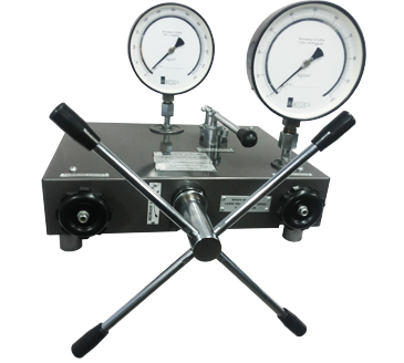
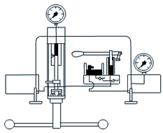
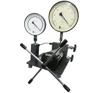
For quick calibration by comparison with Master Gauge. The Master Gauge to be periodically checked on Dead Weight Pressure Gauge Tester. Two Gauge Connectors are provided for connecting master gauge and gauge to be tested to the same hydraulic pressure. Screw Pump to generate pressure in the Circuit. Permits easy and accurate setting of pressure.
MODEL CP-1
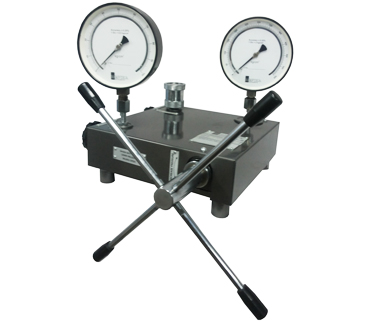
RANGE 0-100 kgf/cm2 | 0-1500 lbf/in2
It is provided with a large capacity screw pump and a removable oil reservoir with isolating valve in a simple line circuit permitting effective air removal
MODEL CP-2
RANGE 0-700 kgf/cm2 | 0-10000 lbf/in2
It is provided with lever operated Priming Pump also giving continuous oil delivery for filling up large gauges or even external piping. Capable of developing 10% of the instrument range and with isolating valves at both ends. It forms a unique closed circuit for effective air removal.
MODEL CP-3
RANGE 0-1000 kgf/cm2 | 0-15000 lbf/in2
It is provided with a larger Priming Pump and a bigger oil reservoir for more oil delivery. Conical ball bearing is also housed in the front plate of screw pump to minimise the linear force while increasing pressure to high values.
MODEL CT-5
RANGE 0-100 kgf/cm2 | 0-1500 lbf/in2
RANGE :0-710 mmHg
It is used for quick calibration with Master Gauge.
The master
gauge to be periodically checked on Dead Weight Vacuum Gauge Tester.
TWO GAUGE CONNECTORSare provided for connecting master
gauge and gauge
to be tested to the same vacuum.
SCREW PUMPto generate vacuum in the circuit. It permits
easy
and accurate setting of vacuum.
VALVEis provided to connect the circuit to the
atmosphere and thus check zero of the gauge.
BASE PLATEof sturdy construction is
provided with legs.
CERTIFICATION / TRACEABILITY :
Calibration is done against Master Dead Weight Pressure Gauge Tester and Master
Dial Pressure / Vacuum Gauges. Our instruments are backed by test certificates
traceable to National Standard to meet the requirements of ISO 9000, QS 14000
and other Inspection Agencies.
| DIAL SIZE | : 150mm, 250mm |
| MOUNTING | : Direct mounting type |
| CONNECTION | : 1/2" BSP or 3/8" BSP bottom connection |
| BOURDON | : Stainless Steel SS 304 / SS 316 |
| MOVEMENT | : Stainless Steel SS 304 / SS 316 |
| SHANK | : Stainless Steel SS 304 |
| JOINTS | : Argon Arc welded |
| CASING | : Aluminium cast |
| WINDOW | : Acrylic |
| DIAL | : Mirror - reflex, White painted with black markings |
| POINTER | : Micro-adjustment, knife-edge pointer |
| ACCURACY | ±0.25% of f.s. |
|
Unit of Calibration :
kg/cm2
|
Unit of Calibration :
kg/cm2
|
|||||||||||||||||||||||||||||||||||||||||||||||||||||||||||||||||||||||||||||||||||||||||||||||||||||||||||||
|
|